7. Lesson 7
7.1. Introduction
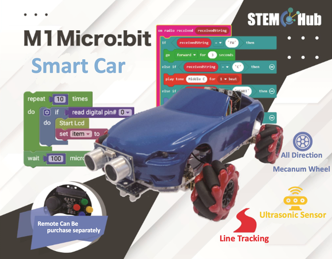
Welcome to Micro:bit Smart Car tutorial! In this course, we will explore Micro:bit and learn how to develop Micro:bit Smart Car by programming
7.2. Learning Target
Let students clearly understand Micro:bit Smart Car’s extension tools and its functions, moreover, understanding its install and block coding method
7.3. Meet the Micro:bit Expansion Tool - Bulldozer
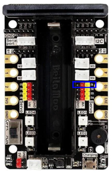
Micro:bit mechanical bulldozer is mainly composed of push plate, servo motor and ultrasonic sensor, and is installed at the front of the car. This time we mainly connect the pins of the servo to the S1 port (the red box shows the different pin bits).
This time, we mainly connect the pin of the servo to the S1 port (pin position shown in the blue box), and generally the dark wire (black or brown) is connected to the black GND port.
7.3.1. Principle and function of mechanical bulldozer
In real life, a bulldozer is an engineering vehicle with a large metal bulldozer in front of it, which can push mud, sand and stones, etc. The position and angle of the bulldozer can be adjusted to suit shoveling, filling, etc. It can also be used to remove obstacles.

Whereas the Micro:bit mechanical bulldozer does not use a sharp dozer, but instead uses a push plate with a hole to handle the job, so as sphere.
7.3.2. To install the bulldozer
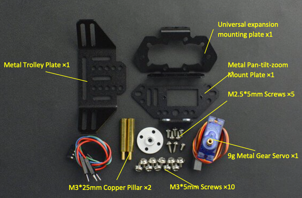
7.3.3. Components – with an ultrasonic sensor:
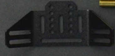
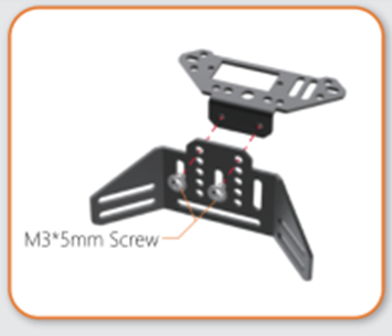
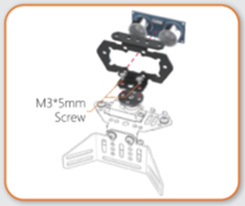
1)Use two M3*5mm screws to connect the push plate and pan-tilt-zoom mount plate.
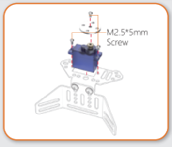
2)Assemble the servo with three M2.5*5mm screws, and install the pan-tilt-zoom mounting plate.
3)Put the ultrasonic sensor into the universal expansion mounting plate, and use two M3*5mm screws to attach the universal expansion mounting plate to the pan-tilt-zoom mounting plate.
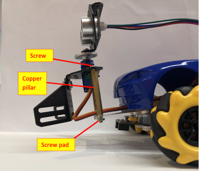
4)Use two screws, two screw pads, and two copper pillars to install the pan-tilt-zoom mounting plate together with the ultrasonic sensor on the car.
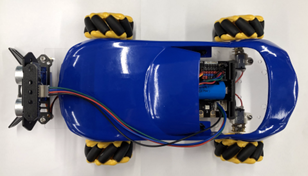
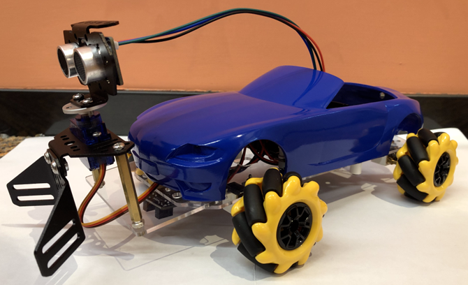
Finished diagram:
7.4. Exercise 1
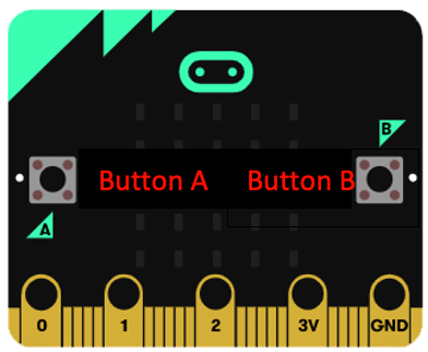
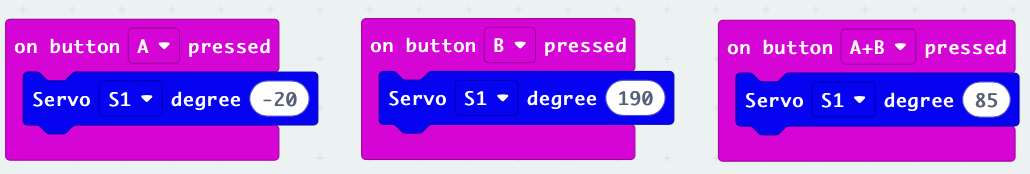
Design a program using the buttons of the Micro:bit board to make the ultrasonic sensor look in different directions.
The A button looks straight to the left (270°), the B button looks straight to the right (90°), and the A+B button looks straight ahead.
Hint:
First adjust the installation angle of the servo so that the angle value of the servo module is 85 as the front
Only using the servo module 0-180 degrees cannot make the servo ultrasonic sensor look to the left and right
Negative numbers and values above 180 degrees must be tried
| Ultrasonic sensor facing direction | Angle value |
|---|---|
| Straight Left | |
| Straight Right |
7.5. Exercise 2
Design a program makes the ultrasonic sensor complete the task, put down the car on the circular field, let the car drive automatically and use the push plate to push all the objects in the field out of the field, and the car cannot go out of bounds.
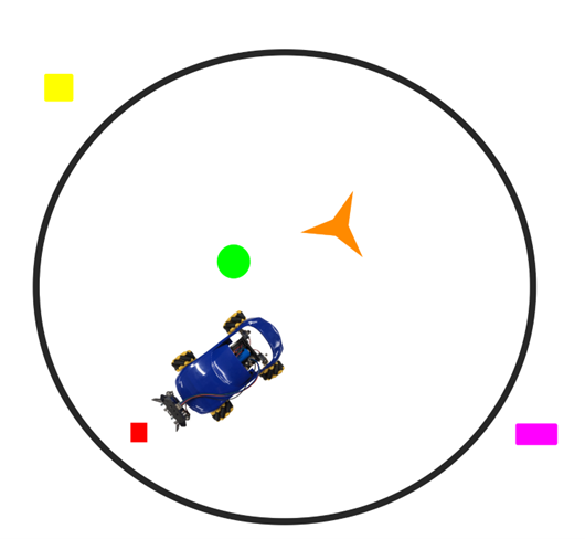
Hint: Refer to Backwards to either side when the car reaches the boundary.
7.6. Answer
7.6.1. Exercise 1
The actual total rotatable angle value of the ultrasonic sensor is about 210 degrees, -20 degrees is the actual 270 degrees, 85 degrees is the actual 270 degrees, and 190 degrees is the actual 90 degrees.
| Ultrasonic sensor facing direction | Angle value |
|---|---|
| Straight Left | -20 |
| Straight Right | 190 |
7.6.2. Exercise 2
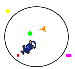
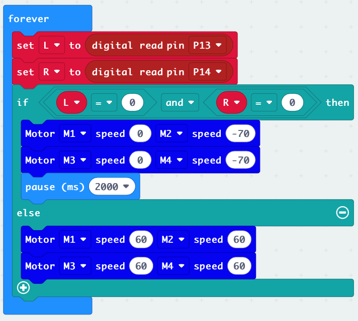
When the car reaches the boundary of the black line, it backs to the back right side for 2000 milliseconds, otherwise it keeps going forward.